lundi 15 avril 2024

8 Ports USB Midi interface.


This topic is a very long-standing one for me. I must have started thinking about it in the early 90s. At the time, the power of microcontrollers did not allow the development of complex systems. I then remember having developed a 68000 system to manage the 8 MIDI ports. I never created this system because I realized that it was far too complex to create and therefore necessarily too expensive.

10 years later, at the beginning of the 2000s, things improved in terms of the possibilities of embedded systems. So I tried to create this multi MIDI port using a micro-controller. I almost got there, but ran into a small problem, it was still difficult to find a circuit offering 8 serial ports and fast enough to manage them.

Everything changed in the early 2010s. At that time, it became possible to find a micro-controller circuit with 8 serial ports and enough power to manage everything. It was then that I looked into ARM type circuits from STmicro. From that point on, the problem shifted from the hardware to myself. In fact, in view of the possibilities of the new circuits, I wanted to add a whole bunch of functionalities, including USB bus management. Then, I entered into a spiral of redefining the functions of the object which, constantly, made me experiment with various solutions, all nevertheless unsatisfactory in my eyes. Unsatisfactory, because of the poorly defined hardware, and/or the software functionalities, which are also poorly chosen.

But, this series of failures allowed me to test a lot of solutions. And, a few days ago, as I was rearranging my stack of synths and rewiring everything, the obvious solution dawned on me. Now, right away, I saw very clearly what system I needed to have on hand to allow me to easily and flexibly wire all of my machines. I also realized that I wasn't far from the real subject, in fact. And that I just had to use all my previous developments and my previous ideas to achieve what I needed.

First, create not a hub or a switch, but simply an 8-port MIDI interface. I already have the prototype almost available. I just need to make some minor modifications to allow my 8 ports prototype to be connected to the USB port. So I have just made the necessary modifications to the circuit. 

The general idea is that it should remain simple to achieve. Thanks to the experience acquired with RISC-V processors during my previous work, I left with this type of processor :

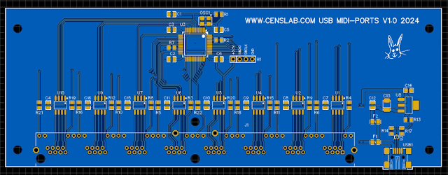
It's a fact, the printed circuit board does not seem very complicated to make. Once the components are implemented, it should look like this:


As you might expect, the MIDI connectors are not shown in this 3D view. In fact, it is not standard MIDI connectors but RJ45 connectors that are used. This is a particular characteristic of my system.
 
The difficulty for me is not the creation of the card but its programming. Working with the USB bus is not always easy. Fortunately, a few years ago I implemented a 2-port MIDI interface on a USB port using an ARM microcontroller from STmicro. So I have a software base, I'm not starting from scratch. Even if this does not guarantee that I will reach the end, I also have no means of debugging the USB bus, I am relying on the experience acquired to complete this subject.


lundi 19 septembre 2022

MIDI SWITCH

 The basic functions of the MIDI switch prototype work well. I'm still developing the system but at the same time, I'm redesigning the printed circuit board. 

The prototype was developed from an Intel OEM FPGA module placed on a motherboard that I created myself. On this motherboard, four connectors connect four small printed circuits each supporting four RJ45 sockets, for a total of sixteen ports.

This way of doing things was perfect for a prototype but not at all suitable for a finished product.
What I particularly appreciate is making it as simple as possible. And since the study from the prototype I experimented with a new type of FPGA more practical to use than Intel circuits, I took the opportunity to redesign the entire switch on a single printed circuit :

The circuit used will allow me to route the MIDI ports but also to perform some processing on the MIDI data. Everything will be programmable using, I hope, a small software running on PC and potentially on MAC.


mercredi 14 septembre 2022

MIDI SWITCH

It's been almost a year I posted anything on this blog. During this period I worked on digital projects more specifically on the theme of retro-computing. I also took the opportunity to discover and use a type of FPGA that is relatively unknown but which I like very much.

I nevertheless started very actively to develop two projects specifically for electronic musical instruments. One of them consists of a 16-ports MIDI rack designed to facilitate the management of the MIDI network within a small music studio.

Although I'm still at the prototype stage, the hardware design is finalized and stable. I am now in the development of the software system. I am progressing step by step in order to create a system offering the essential functions. Subsequently, I will expand the operation by various functions that can be implemented depending on the computing resource that will remain available to me.

This is what the rack looks like:


The challenge is a little bit complicated. A reliable and practical device must be produced at an acceptable cost. And with the current problems of component shortages and rising prices, it really isn't easy!

The second project on which I work consists of the  development of a clone of SP12 or SP1200. In fact, it all started a few years ago with the FPGA implementation of the heart of a Drumulator. Then afterwards I also created the machine's waveform sequencer and finally, I tested the analog sound reproduction. 

It went downhill when I decided to put it all together in a real Drumulator clone. In fact, I realized that it took a lot of work. So I compared the differences between the Drumulator and the SP, and realized that in fact, it was exactly the same thing, except for a few details. 

So I decided to directly create a clone of SP. From my previous experiments, I have adopted a design method that seems more rational to me. But hey, it's a bit more complex than the MIDI switch. But I have high hopes of achieving a good result with the chosen FPGA.


vendredi 5 novembre 2021

AKAI S5000/6000 under Windows 10

I personally own an 'old' S5000 sampler. It is still a very good machine from a sound and functional point of view. It is not because this machine is twenty years old that it is obsolete. The only slightly negative point is that the use of such a machine via the control panel is not particularly very convenient. Reason why AKAI also released the S6000 with detachable front panel:

https://www.soundonsound.com/reviews/akai-s6000-s5000

For this reason, AKAI had also published a software allowing the reproduction of the front panel of the S5000 / 6000 series directly on a PC, thanks to the optional USB interface:

eBay ($235 November 05, 2021)

This software was AKsys. It offered the possibility of controlling the entire control panel through its graphical interface :


Great. Today, the problem is that neither this software nor the driver for the 'S' series samplers are compatible with Windows 10. So is all lost? Of course not!

A French enthusiast, Guillaume Jouffroy, has developed a driver and an application offering the same characteristics as AKsys, S56sys:


This graphical interface allows you to view the contents of the S5000 / 6000 screen live and also of course to directly control the machine as here, example the loading of samples form the internal disk:


A small problem with the software here, the lack of refresh once the operation is complete. We imagine then that s56sys is crashed. This is not the case, pressing one of the eight function buttons refreshes the screen. OK, that's not a problem!

Another problem exists. In the right pane, the sample memory content is not updated either. The solution is simply to quit the application and relaunch it immediately. You don't lose anything since everything happens in the sampler. The solution is just not... very elegant. After that, the memory content of the S5000 is displayed well :


And you can transfer the sample of your choice from the S5000 / 6000 to the directory of your choice on your PC. The transfer from the PC to the sampler is done in the same way.

Warning: the destination directory on your PC must have extended rights. The copy will remain blocked if it is necessary to have administrator rights:


Please note that the transfer is carried out under the USB1 protocol with a theoretical speed of less than 150 KB per second. It's relatively slow ... but it offers a simple and inexpensive way to transfer your samples to the PC for editing or even storage if you don't have specific units on your sampler.

In short, you can perform almost all the tasks of this sampler directly from your PC. After a few hours of use, I can say that this app is very handy.

Another example, the management of the MIDI interface:

And so on...

The license currently costs € 9 (November 05, 2021). How to say: it is almost free!

Given the services provided by this software, there is absolutely no hesitation in acquiring a license!


vendredi 2 juillet 2021

A SMALL MIDI TOOL.

Another problem that really annoys me when I want to quickly jump to a patch on a specific synth. is that it is never easy. You have to go to the PC to play with the mouse, or type on the series of control keys of a particular hardware sequencer. Or more simply, get up from your seat to change the patch directly on the machine.

I decided to create a small simple module allowing to select a MIDI channel as well as a change of patch on the selected channel.

Here is the result of my thoughts on the subject:


Unlike the Midi Merge Box project, here, the system must fit into the MIDI chain. The system cannot therefore be passive and must insert the patch change commands only when the MIDI 'network' is available.

The second challenge consists in power the Patch selector from the MIDI bus. Indeed, such a device which must be inserted in a MIDI chain can be very quickly painful to use if in addition it is necessary to manage the power supply unit.

To do that, it is necessary to develop a system whose power consumption remains below 20mA, ideally below 15mA. this time, I chose a microcontroller that I haven't used for over 15 years but which turns out to be very energy efficient and above all very easy to program / debug.

At the stage where I am developing my little studio, I have now to decide for a mixing console. I would go for a RACK version because I don't have a lot of room in my studio!

What do you think of Yamaha's TF-R rack console?


Tell me if you have any comments on this console ...

jeudi 10 juin 2021

New PSU for the Prophet VS

  The Sequential Circuits Prophet VS is a great synthesizer :


But it is also a machine that is not very well made. Poor quality components, perfectible printed circuits, spreading out of the processor buses inside the device, a PSU that heats up a lot, a very noisy transformer and above all a whole series of very poor quality connectors. Not to mention the 'famous' CEM5530 whose production at the time must be completely out of service today, reason why I had to develop a replacement clone years ago.

The copy I own has only really worked for a few years, after making a lot of changes. And yet, there would be more to do. And precisely, one of the really painful things in this machine, when it works and that one can use it, it is the very important noise which the power transformer generates: very boring.

So, I decided to replace the whole power system of this VS. There were several possible choices for creating a replacement PSU. I decided to create a generic power supply that can be used in other devices, and secure, without handling high voltages. 

I created a low voltage switching power supply with linear regulators on the + 12V and -12V outputs:

Beta version.

Output technical details:

  • +5V     2A (switching)
  • +12V   2A (switching + linear)
  • -12V    2A (switching + linear)
  • RESET signal
  • /RESET signal
  • +5V     BATTERY
  • Power Error indicator
  • Floppy type power connector
Input technical details:
  • 2 x 18V/AC
  • Thermal fuses
Advantages:
  • Precise outputs
  • Low heat dissipation in normal use

I have to admit that it took me several versions to sort out the little issues that I encountered and thus obtain a very reliable and convenient power supply. To install this new PSU, the first thing to do was to remove all the concerned components on the Prophet motherboard:


In my case, I also removed the memory backup battery because I equipped my Prophet with self-backed SRAMs. This avoids any possibility of problem due to a possible corrosion of the battery body which could cause serious damage to the printed circuit:


The components removed from the Prophet motherboard:


'Last' modification, I placed wires for + 5V, + 12V and -12V, intended to be connected to the new PSU:


After that, it only remained to place the new power supply into the Prophet, as well as the new transformer:


Regarding my VS, I saccrified the voltage selector and shortened it to be able to position the new PSU more easily. I obviously kept the fuse holder that I put in place of the voltage selector.

During my first operational tests, I observed some problems with the sound. The red LED on the PSU would light up at times, indicating a loss of regulation. It was normal since I did not have a 2x18V transformer available but only a 2x12V. The + 12V and -12V regulations could therefore not be provided correctly. 

So I ordered and received a few days later a German quality 2x18V transformer. In the meantime I also made the last modifications on the printed circuit of the PSU and mounted this new copy in the VS:


Self congratulation but... I am very satisfied with the result. The PSU works perfectly well. The error LED remains constantly off. The PSU heats up very moderately. Above all, the Prophet no longer emits any operating noise. And that is a real pleasure!

Exterior view:


Funny: the three green LEDs of the PSU illuminate the printed circuit board of the front face, which has the effect of nimbling the 'Enter' and 'Edit Waveform' switches with a green hallo.

If you are interested, this PSU is available. Contact me for more information:

jeudi 11 février 2021

NEW PSU V1.1

I made a few small changes to this V1.0  PSU :

V1.0 with SMD chemical capacitors

Compared to version 1.0, I changed the type of chemical capacitors and switched from SMD models to through-hole models. 

Beyond the fact that chemical SMD capacitors are quite difficult to solder, whether manually or automatically, I have bad experiences with the reliability over time of this type of capacitor.

I also put some distance between the two output terminal blocks to facilitate the insertion of cables on the first terminal block (MAIN_1).

And for fun, a small family photo of the evolution of this type of power supply:


Output technical details:

  • +5V     2A
  • +12V   2A
  • -12V    2A
  • RESET signal
  • /RESET signal
  • +5V     BATTERY
  • Floppy type power connector
Input technical details:
  • 2 x 15V/AC (18V Max)
  • Thermal fuses
Advantages:
  • Precise outputs
  • Low heat dissipation in normal use